Generate Rapid Texture using an image to define contour parameters.
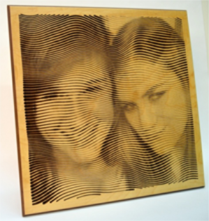
Photo Selection
Color photos yield better results than black and white photos. Black and white images are more uniform and result in more uniform contours. In this example a black and white photo was used and the original image is shown on the left. Several edits were made to the photo to increase the contrast between light and dark areas to improve the Rapid Picture results.


Example
-
 Define the plate dimensions. This example uses a 15" x 15" panel of 0.5" thick material
 -
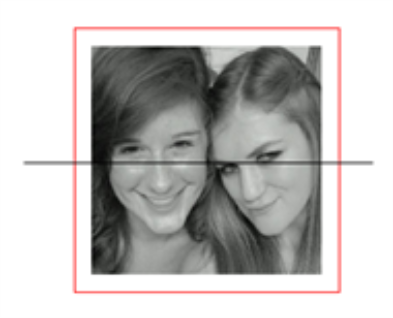
 Import the image into the workspace
 -
 Scale the image to the panel size. For this example the photo size is 13" x 13" to allow for a 1" border
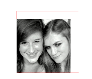
-
Move the image to the center of the panel
With image selected the Hold down Alt + Ctrl and press the 5 Key on the number pad to automatically snap the selection to the plate center. -
 Use the Rectangle tool to create a contour at the plate boundaryEnable Snap to Grid to easily create a Rectangle by Corners that defines the plate boundaries. Note the default grid size is 1 inch intervals.
-
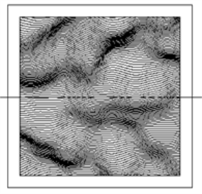
Draw a Seed Contour for Rapid Texture generation
-
Select the Seed Contour and activate the Rapid Texture command

-
Left Click on the image to open the tool selection dialogue. Select the tool that will be used to cut the toolpaths. This example uses a 0.02 engrave tool. Click Accept
-
Define the Whitespace Gap which controls the minimum separation between contours in dark areas of the photo. Click OK
-
An information box will appear with the selected parameters, click OK
-
Define the Rapid Texture parameters
- Parameters for the example pictured
- Position: X = 1, Y = 1
- Size = 13" x 13" (Image Dimensions)
- Wavelength = 3.5
- Horizontal Amplitude = 1.5
- Vertical Amplitude = 0.01
- Offset = 0.15
- Noise Displacement Enabled
-
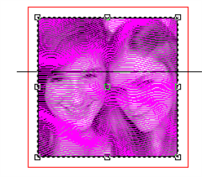
Click Apply to create contours.

-
Select one of the contours, all of the generated contours are grouped at this point. Activate the Engrave command

-
Set the Engrave parameters.
-
For this example the following parameters were used
-
Tool = 0.02" Engrave
-
Depth = 0.01"
-
Follow Contours = Checked
-
Feed Rate = 60 inches per minute
-
-
-
Click OK to generate Toolpaths.
 Group the toolpaths together while they are selected
 -
Apply a routing offset to the panel contour
-
Example parameters
-
Tool = 1/4" End Mill
-
Depth = 0.5"
-
External = Checked
-
-
-
Apply an Engrave toolpath to the panel contour to add a beveled edge to the design
-
Example parameters
-
Tool = 90 Conic
-
Depth = 0.2"
-
3D Engrave Toolpath = Checked
-
Internal = Checked
-
-
-
Use the Simulate 3D
 tool to create a rendered view of the toolpaths
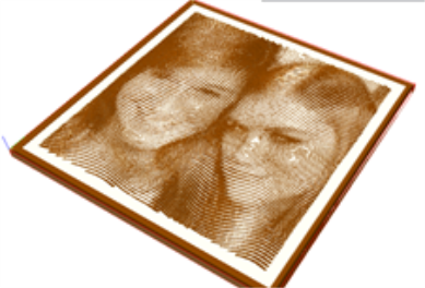
-
The project is now ready to cut