
Cree una trayectoria de herramienta que discurra por el interior o el exterior de un contorno cerrado. La trayectoria de la herramienta se desplaza del contorno en el radio de la herramienta para que el borde de la superficie de corte se alinee con el perímetro del contorno.

![]()

Si una herramienta de corte no puede seguir la forma del contorno en una esquina o curva cerrada, la trayectoria de la herramienta seguirá la curva suave más cercana posible.

Al activar la herramienta Desplazamiento de ruta se abrirá el diálogo de estrategia. Utilice el diálogo de estrategia para añadir y eliminar cortes.
Establezca los Parámetros de corte para cada corte para definir cómo se generará el Desplazamiento de ruta.
Pasos
-
Seleccionar el contorno que debe seguir la trayectoria de la herramienta
-
Activar el comando Routing Offset
-
En el cuadro de diálogo Desplazamiento de la hoja de ruta, seleccione la herramienta deseada de la lista Herramientas y seleccione Añadir herramienta
La lista Ordenar por ordena la lista de Herramientas por parámetro o tipo de herramientaLa primera herramienta de la lista siempre se define como la herramienta Áspera, y suele ser la herramienta de corte principal. Las herramientas adicionales sirven como herramientas Limpia o Fina -
Definir una Profundidad para la herramienta seleccionada en la ventana de listado de herramientas.
-
Añadir cortes adicionales utilizando otras herramientas según sea necesario
-
Establecer los parámetros de desvío de ruta
External (Male) When checked, the toolpaths will follow the outside of the contour Internal (Female) When checked, the toolpaths will follow the inside of the contour Weld Offsets When checked, overlapping offsets will be welded together to form a single toolpath group. If unchecked, overlapping offsets will remain unchanged Sharp Corners Offset toolpaths from square corners are rounded by default, allowing for smoother machine operation without rounding the contour perimeter. When checked, this parameter forces toolpaths to be generated with square corners. It is generally not recommended to enable this paramter. Inlay If checked, the toolpath defines either the socket for an inlaid piece of a different material (if the toolpath is set to Internal), or the cut that will separate the inlay itself from the plate (if the toolpath is set to External).
Because a round bit is being used to cut out both pieces, both the male and female toolpaths need to take into account the dimension of the tool. This changes the shape of the toolpath, particularly in corners.If this option is checked, the Inlay Gap parameter displays. This parameter indicates the size of the gap that will exist between the inlay and its socket.
Bridges When checked, generated toolpaths will leave small tabs of material uncut to connect the design to the remaining material sheet. Additional parameters are activated to define the bridge shape when this option is checked. -
Click OK
Bridges
Bridges are lifts in Routing Offset toolpaths that create tabs that maintain the connection between part being cut and the material it is being cut from. Bridges improve stability so the part does not move while being cut. The tabs are trimmed away after cutting the part.
Bridge Parameters
| Tipo | Definir la forma del puente. Cada forma tiene ventajas para diferentes materiales, mientras que los puentes lisos permiten el funcionamiento suave de la máquina |
| Longitud | Longitud de cada puente. Los puentes más largos tienen mayor resistencia, los puentes más cortos funcionan bien en materiales más resistentes |
| Altura | Altura de cada lengüeta del puente. Otro parámetro que influye en la resistencia del puente |
| Por número | Definir el número de puentes en un desplazamiento |
| Por longitud | Definir la distancia entre cada puente |
| Manual | Definir ubicaciones específicas de los puentes a lo largo del desplazamiento. |
Formas de puentes
| Ascensor | 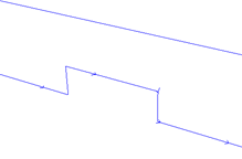 |
| Rampa | 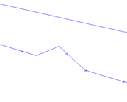 |
| Suave | 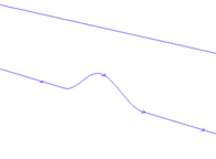 |
| Rampa Mesa | 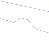 |
| Mesa lisa | 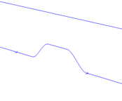 |