Most of the same strategies used on other toolpaths can be applied to 3D designs, including Routing Offset, Engrave, and Hatch and Island Fills. 3D toolpaths require a few additional parameters to define how the relief influences the toolpaths.
Strategy Parameters
The parameters required for 3D toolpaths are automatically enabled when one or more reliefs are selected when activating a strategy. When checked, the Apply to Relief parameter displays the four additional parameters that define how toolpaths are applied to a relief.
| Apply to Surface |
Toolpaths will follow the relief surface and the depth of cut will be adjusted to follow the relief. If no relief is selected, the depth is defined by the cut parameters depth. The cut depth defines the maximum depth of the toolpaths. |
||||
| Carve into Surface |
Toolpaths follow the relief while using the cut depth to define how deep to cut into the relief. Enabling this parameter enables two more.
|
||||
| Apply Overcut (Fills Only) |
Compensate for the dimensions of ball end mills by allowing toolpaths to extend beyond the part boundaries. Without this option, the design would leave the radius of the ball nose uncut around the edges. A good rule of thumb is to set overcut to a little less than 1/2 the tool diameter on the finish pass
|
Cut Parameters
Offset from Surface
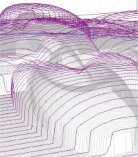
Set how close the toolpaths will follow the surface of the relief. Typically defined for rough cuts to ensure the roughing pass does not damage the finished surface. Offset is determined by the type of material, type of tool, and how fast the roughing pass should run.
The image below shows toolpaths with a 0.20 offset.
Step Rough
Available for Hatch and Island Fills. Create optional toolpaths to rough out the relief surface before creating the finish toolpaths.
This method is more efficient than standard 3D rouging passes because it creates 2D toolpaths at multiple pass depths to remove as much material as possible at that depth. The 2D toolpaths can typically be defined using higher feed rates than 3D toolpaths.
An important consideration when applying a step rough is that the ball end mill used for the final pass must be capable of cutting the steps that remain after the step rough. The height of each step is the difference between the depths of each pass in the step rough.
Key 3D Toolpath Concepts
Three axis routers create 3D objects by making incremental cuts with a ball end mill to remove material from the finished surface. The size of the tool, the amount of overlap, and how much detail is required are all constraints. The relationship is the smaller the tool, the larger the overlap, and the finer the detail, the longer the design will take to cut.
In general the finish cut should be run as a single pass because it takes the longest time to run. The rough strategy clears material out of the way for the final cut and goes a long way to getting the job done. It is important to use the EnRoute visualization tools to ensure the job will cut correctly because the depth of cut can vary greatly across large 3D surfaces. It is easy to get into trouble using a small tool to make a deep cut, but EnRoute provides tools to avoid these situations.
Overlap
It is important to select the proper overlap percentage when milling a 3D surface to achieve the desired surface finish. Milling 3D relief surfaces requires the use of a ball end mill to cut smooth surfaces. The spherical surface of the tool creates small grooves in the finished surface which vary in size depending on the amount of overlap. As overlap increases, the tool marks are reduced while increasing the cut time. The goal is to balance cut time and cut quality.
The best way to determine overlap is to cut a test relief using the same material as the job to estimate cut time, the surface quality, and the amount of finishing work.
Typical overlap values range from 80% on larger reliefs with larger tooling marks, to 95% for small reliefs with a smooth finish.